Definition: A Half subtractor is known as a combinational circuit that produces a difference of two, 1-bit binary numbers. More specifically we can say, that it subtracts the two binary values at its input in order to generate a difference of the two values at its output using a borrow bit if required.
Thus the half subtractor circuit has two inputs, minuend and subtrahend and two outputs one is the difference while the other is borrow.

Content: Half Subtractor
Binary Subtraction
We know binary addition of two, 1-bit values are performed by a half adder. However, in the case of the addition of two 1-bit values, a carry bit is generated. But in the case of subtraction, a borrow bit is considered.
We all are already aware of the way by which two numbers are subtracted from each other. Basically, in order to get the difference of two values, the subtrahend must be subtracted from the minuend.
However, in case, the subtrahend is a greater value as compared to the minuend, then borrow from the next column is taken according to the base value of the system. This same format is followed by a half subtractor circuit in order to produce the difference of 2, 1-bit values.
Let us take an example of subtraction of two, base-10 numbers:
Suppose we have to subtract 56 from 93

Here from the above example, it is clear that the minuend of the first column is smaller than the subtrahend. So, 6 cannot be subtracted from 3. Hence, in this case, a borrow is to be considered from the next column. This borrow term is nothing but the value of the base or radix system.
As we have considered here a base-10 system, then the borrow will be a 10. So, this borrow will make 13 of 3. Then 6 of the subtrahend is subtracted from 13 of the minuend. Thereby providing 7 as the LSB of the output. Now, the next column bit i.e., 5 is subtracted from 8. This provides 3 as the other bit of the output value.
Hence the difference of the above-discussed example will be 37. Along with a borrow of 10 which is nothing but the base value of the system.
Similarly, subtraction of binary values i.e., with base-2 is performed.
Let us take an example of two binary values that are to be subtracted:
Suppose 01 is to be subtracted from 10
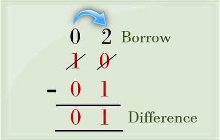
Here in the above example, we can see that binary term 10 is the minuend and 01 is the subtrahend.
So, when we perform the subtraction of LSB of subtrahend from the minuend. Then we see that 1 cannot be subtracted from 0. So, we take a borrow from the next column.
This time the borrow will be a 2 as it is a base-2 system and the next bit has value 21. So, when 1 of the subtrahend is subtracted from the borrowed value of minuend i.e., 2 then it will produce 1 as the LSB of the output.
Further the MSB of the subtrahend i.e., 0 is subtracted from 0 of the minuend. Thereby providing 0 as the MSB of the output. Thus the difference value achieved at the output will be 01 with a borrow bit represented as 1.
Similarly, a half subtractor circuit performs the subtraction of binary values.
Truth Table of Half Subtractor
It is basically considered that truth tables are the easiest way to understand the operation of digital circuits. As it clearly specifies the various result generated from certain combinations of the input values.
So, let us have a look at the truth table of 2 input half subtractor.
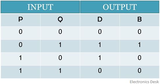
Here, P and Q are the two inputs to the half subtractor while D and B represent the difference and borrow bits respectively at the output.
So, from the above table, we can say that,
- 0 – 0: When 0 is subtracted from 0 then it will generate 0 as the difference value. And also making the borrow bit 0, as no borrow is required for this particular subtraction.
- 0 – 1: When 1 is to be subtracted from 0, then we know in such a case a borrow is needed to produce the difference. So, 1 is now subtracted from 21 i.e., 2. This will produce the difference as 1. Along with that a borrow 1 will be displayed at the output, for this particular subtraction.
- 1 – 0: When 0 is to be subtracted from 1, then the difference can be easily generated as 1, without the need of borrow bit. Hence the table represents 1 as the difference and 0 as the borrow bit.
- 1 – 1: The binary subtraction of 1 and 1 will provide 0 as the difference. And as no borrow is required to be taken for this particular operation. Thus the borrow bit will also be 0.
K-map for Half Subtractor Circuit
Let us now move towards the K-map representations of the two outputs for difference bit
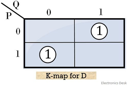 So, on grouping each 1 separately, due to the absence of any appropriate pair. We will get the first and second implicant,
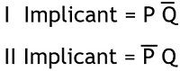
Therefore, the realized expression for ‘difference’ bit will be:
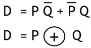
The above equation simply illustrates the X-OR operation performed by the two inputs of the half subtractor.
Further, making the K-map for ‘borrow’ bit
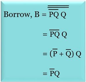
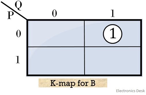 So, the realized Boolean expression for borrow bit will be:
![]()
These are the two equations of difference and borrow bits at the output of the half subtractor.
Logic circuit of Half Subtractor
The figure below represents the logic circuit of half subtractor that performs the subtraction of two binary value of 1 bit each using X-OR, AND & NOT gate:
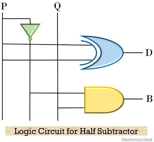
As we have already explained that the generated difference term of the half subtraction is nothing but the X-OR operation. Thus in the logic circuit, the two inputs are provided at the X-OR gate to generate the difference of two, 1-bit values.
However, the logic circuit of half subtractor can also be implemented using only either NAND or NOR gate
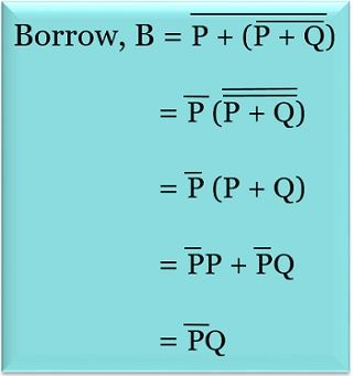
So, let us also have a look at the logic circuit of half subtractor using NOR gate only:
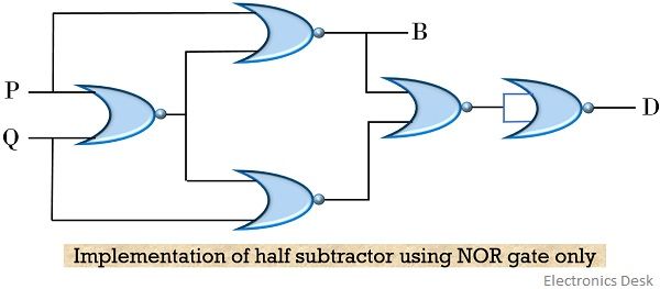
Also, have a look at the implementation equation:
For Difference bit:
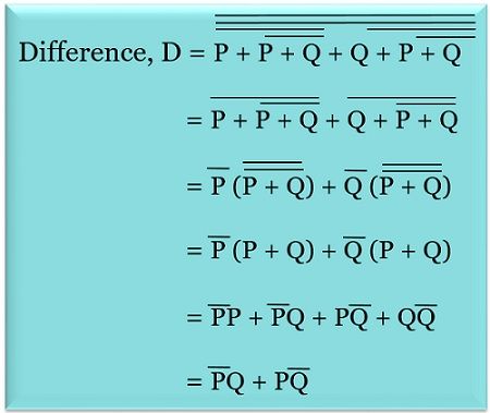
For Borrow bit:
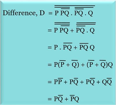
Further, see how half subtractor circuit can be implemented by the use of only NAND gate:
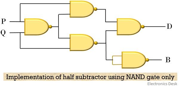
The implementation equation of half adder using NAND gate is given below:
For Difference bit:
For Borrow bit:
It is to be noted here that a half subtractor can only execute subtraction of 2 bits and does not entertain the borrow term from any previous subtraction. So, to overcome this disadvantage full subtractor circuit is utilized.
This is all about the basic functioning and logic circuit of half subtractor.