Definition: Half adder is a combinational circuit that is used to add two binary numbers of one-bit each. It does not hold the ability to consider the carry-in generated from previous summations. The addend, when added with the augend, provides sum and carry (if present).
Half adders are used in addition of LSB of the numbers only.
In simple words, we can say, that it adds two binary numbers of 1 bit each and generates the output as the sum and carry. It is noteworthy that, not all summations bring a carry with it, however, if it holds a carry then the carry bit is represented as high otherwise low.

Content: Half Adder
Binary Addition
We know that adding two numbers will generate the summation of the two as a result. And we all know the basic method used for adding two numbers.
When subtraction of two numbers is performed then basically difference and borrow are the terms that are needed to be considered. This we have already discussed in half subtractor.
Always the addition of two numbers begins with the least significant column and ends with the most significant column. However, we have recently discussed that half adder performs the addition of only single bit numbers.
At the time of addition of two-bits in case, a carry bit is generated then it gets added with the next column bit that is to be considered. This is the way to perform basic addition.
Let us take an example to understand how the addition of decimal number takes place. Then we will move further towards the addition of binary values.
Suppose 56 is to be added with 35
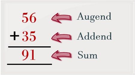
Here, we can see that we have started the addition with the least significant column. So, 6 is added with 5 and this summation generates 11 as its output. But while writing the result we simply write the LSB of the summation as the least significant bit of the output and the MSB acts as the carry bit.
So, when the summation of the most significant column is considered then carry from the previous addition is considered. Thereby we get the summation as 91.
Let us now consider two binary values in order to understand the binary addition.
Suppose 110 is to be added with 100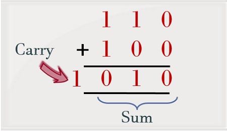
As we can see the addition of 0 and 0 generates 0 as the sum. Further when the next bit is considered the summation of 1 and 0 will give 1 as the output. But when the addition of 1 and 1 is performed then it will produce 0 as the sum and carry bit 1 will be generated.
We will discuss later how the addition of 1 and 1, provide 0 as the sum and 1 as the carry.
Truth Table for Half Adder
In the previous section of this article, we have discussed, how the addition of decimal and binary numbers take place. But in decimal as well as binary addition we have considered more than 1-bit number. However, the half adder operates on only a single bit.
So, let us now consider the truth table for half adder showing binary addition of 1-bit numbers:
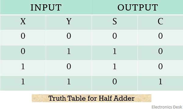
Here, X and Y are the two, 1-bit binary numbers applied at the input of the half adder while S and C denote the sum and carry bits respectively.
On considering the above table,
- 0 + 0: We know the binary addition of low and low i.,e 0 and 0 will give 0 as the output without generating a carry. So, in this particular case, the bits representing the sum and carry both will be 0.
- 0 + 1: The addition of 0 and 1 generates 1 as the output which is represented by the sum bit in the above table. Whereas as no carry is generated thus carry bit will be 0.
- 1 + 0: Like in the previously discussed case here also the addition of 1 and 0 will give 1 as the sum and 0 as the carry for the respective addition.
- 1 + 1: When the half adder adds 1 with 1 then it produces 0 as the sum and 1 as the carry. Now, let us understand the logic behind how the addition of 1 and 1 will generate 0 as the sum and 1 as the carry.
The circuit inside the half adder performs the addition of binary values using positional weight as shown below:
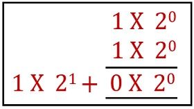 As we can see clearly, the addition of 1 and 1 is providing 0 as the sum and 1 as the carry. We know generally 1 and 1 on addition gives 2. So, one can write 2 in the simplified form using respective positional weight as
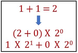 And while writing the desired result the position weight is neglected. This is the reason why we get 0 as the sum of 1 and 1 and 1 as the carry. So, in this way, the circuit of a half adder operates.
K-map for half adder
Now, by considering the truth table for half adder one can have the desired K-map for both sum and carry bit.
The figure below represents the K map for sum bit i.e., S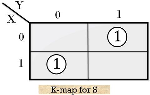
So, the desired implicants for the above given K-map will be
Therefore, the realized Boolean expression will be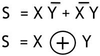
From the above expression, we can say that the summation performed by half adder is nothing but the X-OR operation of the two inputs.
Moving further, consider the K-map for ‘carry’ bit i.e., C
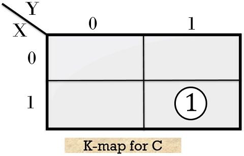
Hence for this particular case, the realized Boolean expression will be![]()
These are the Boolean expressions for sum and carry bit generated by the half adder.
Logic circuit for Half Adder
The figure below represents the circuit representation of half adder by making use of X-OR & AND gate:
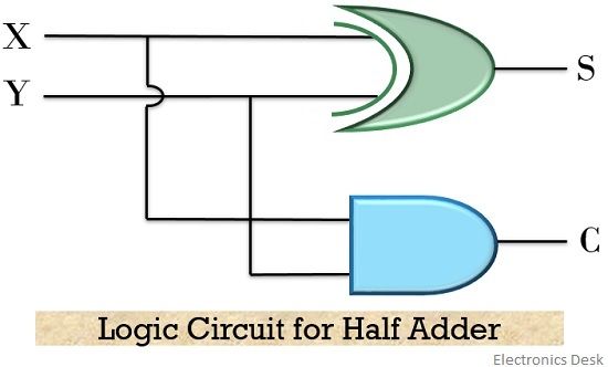
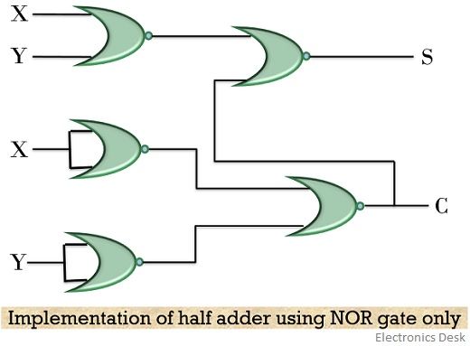
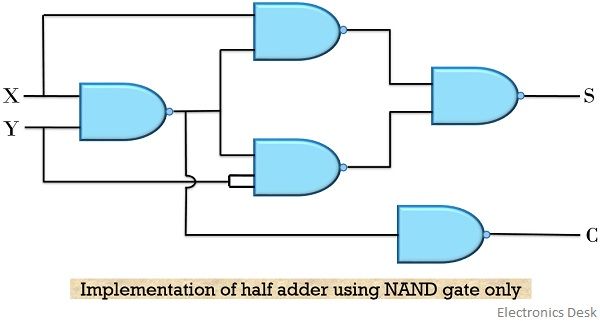
The above-discussed logic of half adder can also be realized by the help of either NOR or NAND gate only.
Let us have a look at the circuit representation of half adder using only NOR gate
Also, the figure below represents the circuit of half adder using NAND gate only
So, from the above discussion, it is clear that adders perform the addition of bits but half adder can only add single bit numbers. Therefore, for the addition of more than single-bit numbers, full adders are used.
Hello,
I have found this article quite useful. Thank you.