Definition: Klystrons are a special type of vacuum tubes that find applications as amplifiers and oscillators at microwave frequencies. Its principle of operation is velocity modulation. Thus the device used for amplifying microwave signals is known as Two-cavity Klystron.
In the year 1937, American engineers Russell and Sigurd Varian developed klystrons. Basically, the operating principle of Klystron is such that the kinetic energy of a moving electron beam is utilized for amplifying and generating microwave signals. TWT i.e., Travelling Wave Tubes are also used for amplification of RF signals and have similar applications as klystrons. But in TWT, a continuous interaction is maintained between the field and electron beam. While in klystrons interaction between the two is allowed to occur only at the cavities of the structure.
Klystrons are majorly classified as:
- Two-cavity Klystron
- Reflex Klystron
Here in this article, we will discuss the construction and working of the two-cavity klystron amplifier.
Content: Two-cavity Klystron
Operating Principle of Two-cavity Klystron
As we have already discussed in the introduction that Klystron is based on the principle of velocity modulation. Thus two-cavity klystron amplifier utilizes the kinetic energy of moving electron beam for signal amplification.
The variation in the velocity of electrons while moving inside the tube is known as velocity modulation. This velocity modulation permits bunching of electrons while propagation. So, the combined energy of bunched electrons is transferred at the output thereby providing an amplified signal.
Construction
The figure below represents the structure of a two-cavity klystron:
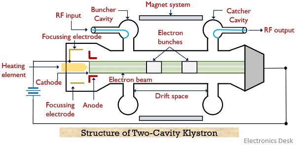
As we can see that the above figure consists of 2 cavities namely the buncher cavity and catcher cavity. The RF signal to be amplified is provided at the buncher cavity. The electron gun comprises cathode, heating element and anode. The electron beam is produced by the cathode by making use of a heating element and the high positive potential at the anode provides the required acceleration to the electron beam initially. The region between two cavities is known as drift space.
To allow focussed propagation of electron beam inside the tube an external electromagnetic winding is used that generates a longitudinal magnetic field. This is done in order to prevent the spreading of the beam inside the tube. The amplified RF signal is achieved at the catcher cavity. Also, a collector is present near the second cavity that collects the electron bunch.
Working of Two-cavity Klystron Amplifier
Consider the above-shown figure of two-cavity klystron amplifier.
Initially, electrons are emitted from the electron gun and the anode present in the structure provides the desired acceleration to the beam.
- In the absence of any RF input, the electron will tend to move with their respective uniform velocities to reach the catcher cavity and gets collected at the collector.
- But when external RF signal is applied at the input of the buncher cavity then this causes the generation of a local electric field inside the tube.
This electric field causes the bunching of electrons as the field applies acceleration and deceleration to the moving electron, according to the polarity of the signal by which the field is generated.
Basically, the reason for causing acceleration and deceleration is that when the direction of movement of an electron is opposite to the direction of the field, then, in this case, the electrons experience a decrease in their moving velocity. However, if the generated electric field and the direction of movement of the electron are the same then, in this case, the electrons experience increase in the velocity of their movement.
Let us now understand in detail how this increase and decrease in velocity causes bunching of electrons:
- When the negative half of the RF signal is provided as input to the buncher cavity then the moving electrons experience a repulsive force due to the presence of a negative charge at the entering plate of the buncher cavity.
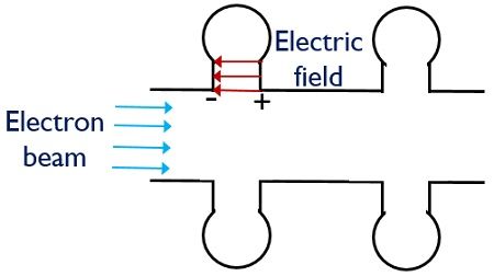
Or we can say, that due to the negative half of the input the generated field will be in a direction opposite to the direction of the movement of electrons. So, because of the opposition offered by the field, the moving velocity of electrons gets reduced. - Further when the positive half of the RF signal is provided then the positive potential at the first plate of the cavity applies attractive force to the moving electrons. More simply, for the positive half cycle of input, the generated electric field will be in a direction similar to the direction of electron movement.
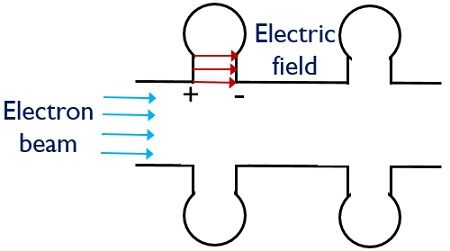
So, this leads to an increase in the moving velocity of the electrons.
Thus, combinely when we consider both the cases then the electrons that were emitted earlier by the gun will be decelerated. While the electrons emitted later will be accelerated. Thus all the electrons while moving with different velocities get bunched in the drift space. This change in the velocity of electrons while moving due to RF input is known as velocity modulation. Once the electron bunching is done then the catcher cavity present at another end of the tube absorbs the beam energy.
It is to be noted that to find the position of the catcher cavity transit time of the bunches must be considered. This is so because the catcher cavity must be present at a sufficient distance from the buncher cavity so that bunching can be attained in the drift space. Further, once the energy is transferred to the catcher cavity then electrons (now with low energy) gets collected at the collector.
Applegate Diagram
The figure below shows the Applegate diagram that represents the bunching of electrons moving with different velocities:
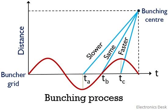
The electron travelling inside the tube under the absence of external fields acts as the bunching centre. Also, the electrons moving due to the influence of the positive half cycle of the signal reaches faster. While the movement due to the negative half cycle is retarded. Thus the figure represents the bunching process at a certain point and at a specific distance inside the tube.
Applications
The two-cavity Klystron finds application in satellite communication, UHF TV transmitters as well as radar systems, wideband high power communication and troposphere scatter transmitters etc.
Very nice explanation
Really this material is helpful. All points are Crystal clear.
This is of great help. Thanks!