Definition: The type of antenna which is formed by connecting long wires in the orientation of a rhombus is known as a rhombic antenna. Its basis of operation is similar to travelling wave radiator. It is also known as a diamond antenna. These are highly directional broadband antenna that radiates maximal power along the axis.
Rhombic antenna generally operates on high frequency and very high-frequency ranges. The operating range exists between 30 MHz to 300 MHz.
These antennas have a quite large structure thus is used in applications where the placement of the antenna is not an issue.
Content: Rhombic Antenna
- Construction
- Working
- Radiation Pattern
- Arrays of Rhombic Antenna
- Advantages
- Disadvantages
- Applications
Construction
A rhombic antenna is a type of travelling wave antenna which utilizes the principle of travelling wave radiator.
It consists of 4 conducting long wires connected in the form of rhombus or diamond. The complete antenna structure is placed horizontally above the surface of the ground.
A rhombic antenna may also be considered as a combination of 2 V antennas or inverted V antennas forming an obtuse angle.
The figure below represents the rhombic antenna:
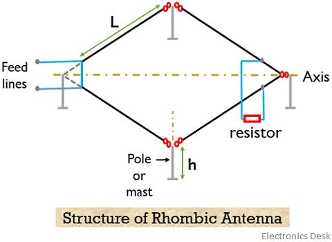
The excitation to the antenna is provided through feed lines. This feed line can be two-wire transmission lines or coaxial wire that excites the whole structure.
Also, to avoid reflections of the travelling wave the opposite end of the antenna wrt feed line is terminated with a properly adjusted resistor. This leads to cause the absence of standing waves in any of the legs of the antenna. The value of load resistance is generally around 600 to 800 Ω.
While designing the rhombic antenna, necessarily it has to be kept in mind that length of all the four conductive wires must be equal, ranging between quarter to one wavelength or more. However, the opposite acute angles of the rhombus must be equal.
The physical form and the size of the antenna are decided by the length of the side and the angle between the vertex.
The feed point and the terminating point of the antenna must be properly aligned as the line joining the two forms the axis of the antenna.
Generally, the antenna is terminated with a value equivalent to characteristic impedance thereby causing the non-resonant condition to establish. Thus radiation characteristics of the antenna are unidirectional.
Thus we can say a properly designed antenna provides maximal radiation in the direction of the axis of the antenna and the wave is polarized in the plane of the rhombus.
Working of Rhombic Antenna
We have already discussed that these operate on the principle of travelling wave radiator. So, when the power through the feed lines either two-wire transmission line or coaxial line is provided to the antenna. Then the generated current travels through the legs of the rhombic antenna.
These current through the antenna generate radio waves that progress in one direction through the legs of the antenna.
We have already discussed that resistive termination is done at the end of the antenna. However, sometimes the terminating end is kept open. This is so because terminating the end reduces reflections of the transmitted wave. But on resistive terminating, a certain amount of power is wasted. This power loss is around 35 to 50%.
In the same way if despite terminating we kept the ends open then this causes the reflection of the waves back towards the feed point.
Thus in case of the rhombic antenna, the losses are almost equivalent in both the cases.
However, in case of open ends, the antenna exhibits bidirectional behaviour. As the radiation is emitted not only in the front direction but also in the back direction.
While if the rhombic antenna is resistor terminated then the antenna possesses unidirectional nature and the radiation is perfectly radiated in the forward direction only. Thereby supporting point to point communication.
Radiation Pattern
The rhombic antenna provides the highest gain along its main axis joining the feed point and terminating end. And the horizontal rhombic antenna provides horizontal polarization.
The figure below represents the radiation pattern: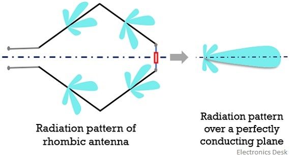
Here as all the major lobes get combined together thus we achieve a unidirectional radiation pattern in one direction only.
It is to be noted here that if the antenna is present close to the ground then due to this the elevation will shift a bit in the upward direction, where the polarization is horizontally intact to the axis.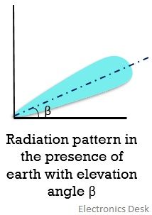
Arrays of the rhombic antenna
Till now we have discussed single wire rhombic antenna but it only suits reception applications. This is so because a single rhombic antenna exhibits low efficiency.
Thus if it is used for transmitting applications then around 40% to 50% of the transmitted power gets wasted in terminating the load.
However, this low-efficiency drawback of rhombic antennas either due to load termination or presence of minor lobe due to open ends can be overcome by using arrays of rhombic antennas.
So, the rhombic antennas can be connected either serially or parallelly as shown below:
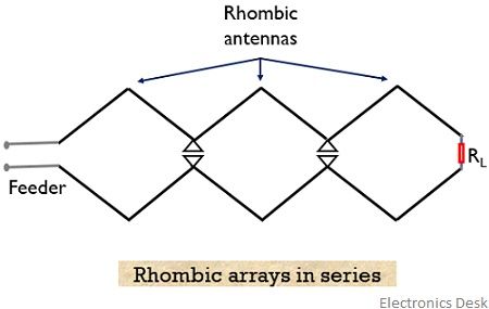
The combination of multiple antennas serves as an arrangement that provides combined directivity thereby increasing the radiation efficiency to 90% or more, which was 50% to 60% in case of a single antenna.
Advantages
- The structure of the antenna is quite simple and it is cost affordable.
- It provides high directivity by radiating most of the power along the main axis.
- It provides efficient long-distance radio communication when installed in a large space.
- The offered input impedance is quite large.
- The radiation pattern and input impedance remain constant for a large range of frequency.
- These can be easily switched from one working frequency to another during operation.
- It suits long-distance F-layer propagation due to low vertical radiation angle.
Disadvantages
- The required area for the installation of the rhombic antenna is quite large.
- The transmission efficiency is quite low as a large amount of power is wasted in terminating the load.
However, when multiple rhombic with definite spacing are placed on the same mast then this somewhat overcomes the disadvantage of lower efficiency to a large extent.
Applications
Rhombic antennas are used in high frequency and very high-frequency signal transmission. Generally, these are suitable for point to point communication in case of long-distance skywave propagation.