Definition: Thyristor (SCR) is a semiconductor device that performs the action of switching as well as rectification. It is a 4 layer and 3 junction device formed by the combination of alternating p and n-type semiconductor material.
Thyristor is a word formed by the merger of thyratron and transistor. As it exhibits the rectification action of thyratron as well as controllability as that of the transistor. It is a 3 terminal device i.e., anode, cathode, and gate. For the conduction to take place gate trigger pulse is necessary. Unidirectionality is the major property of thyristor. This means that it permits the flow of current in simply one direction.
Though there exists a large classification of the thyristor, however, SCR (Silicon Controlled Rectifier) is considered to be the most crucial member that belongs to the thyristor family. Thus, SCR is generally referred to as a thyristor.
Symbol of Thyristor
The figure below represents the symbolic representation of a thyristor (SCR):
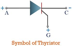
Its symbol is almost similar to a normal diode but the only variation present over here is the presence of a gate terminal that is used to trigger the circuit. As we have already discussed that it is a 3 terminal device, that includes anode terminal, cathode terminal along with the gate terminal.
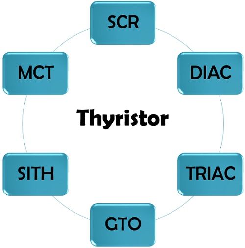
Types of Thyristor
The devices that come under thyristor family are given below:
Construction of Thyristor
Thyristor is a 4 layer and 3 junction device which is majorly composed of silicon as its basic material. Its construction almost resembles like a normal transistor. But, unlike transistor, it comprises of 4-layer. It is formed by back to back joining of two transistors having different configurations. This means by the combination of one PNP and one NPN transistor.
The figure below represents the structure of thyristor having four layers i.e., P-N-P-N:
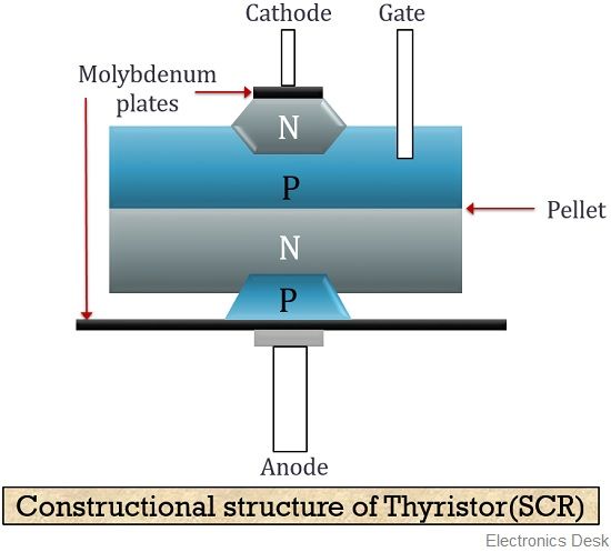
Here, the bottom-most p region represents the anode and the top-most n region shows the cathode terminal. The two regions form a connection with the cathode and anode terminal with the help of molybdenum plates. Hence, we achieve a 4-layer structure comprising of 3 junctions. As we have already discussed that it is a switching device and we know that a switching device must possess a very small leakage current. Also, silicon exhibits a smaller value of leakage current than germanium thus is used in the fabrication of SCR.
Thyristor Working (Operation)
A thyristor (SCR) is composed of two p and two n-type of semiconductor material thereby generating the 4-layer structure.
The figure below represents the two transistor analogy or we can say a simplified form of thyristor:
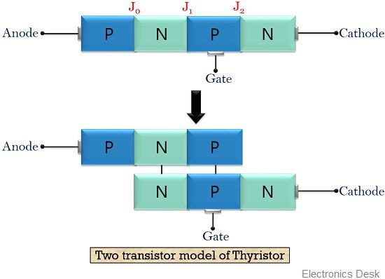
Here, the above figure clearly represents that the collector of the first configuration of transistor acts as a base for the second one. Similarly, the collector of the second configuration of thyristor functions as the base for the first one.
It has majorly 3 modes of the operation let us move further to have a clear idea about how the thyristor operates.
When the anode terminal of the device is connected to the positive terminal of the battery and cathode forms a connection with the negative terminal of the battery. Then due to this, junction J0 and J2 become forward biased but at the same time, this forward connection makes the junction J1 reverse biased. The figure below represents this forward connection clearly:
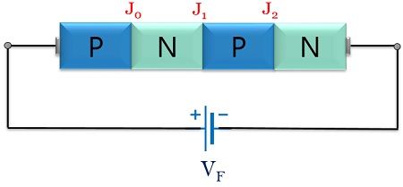
Due to forward biasing junction J0 and J2 allows the movement of carriers. But the intermediate junction J1 because of reverse applied potential generates a wide depletion region and blocks the flow of majority carriers through it. However, a very small leakage current due to the movement of minority carriers flows through the device. But, this current is not enough to drive the circuit. So, despite providing forward voltage the device does not conduct. This is known as forward blocking mode or off mode.
The next condition arises when the anode terminal of the thyristor is connected to the negative battery terminal and the cathode is connected with the positive terminal of the battery.
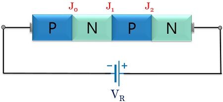
This causes the junction J0 and J2 to get reverse biased but at the same time due to such supply, the junction J1 comes to forward biased condition. So, the reverse biased junction J0 and J2 does not allow the flow of current to take place. Hence, a very small amount of reverse current i.e., leakage current flows through the device. This state of the device is known as the reverse blocking mode or off state.
Proceeding further the actual operating mode of thyristor arises when an external gate pulse is provided to it. Here sufficient positive voltage is provided to anode and gate with reference to the cathode.
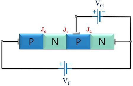
In the above figure, we can clearly see that a forward voltage is provided to the gate terminal with respect to the cathode terminal. Now, in this case, the junction J0, J1 and J2 all comes in forward biased condition. So, the majority carriers start drifting to the collector region of transistor Q1. And as we know that collector of Q1 forms connection with the base of transistor Q2. This base current drives the transistor Q2. Also, the junction is forward biased, so the majority carriers drift to the collector of Q2. In this way, a large current flows through the device. Thus, by applying gate trigger pulse, large electric current flows through the thyristor. This state is termed as forward conduction mode.
Now, even if we remove the gate voltage then also this cumulative action will take place and the current flows through the device once it reaches the minimum value. This minimum current is known as latching current.
Now the question arises then what must be done in order to off the thyristor once it gets on?
So, the answer to the above question is by reducing the anode current up to its lowest value which is called holding current. Thus, a reduction in anode voltage will bring the thyristor again to its forward blocking mode.
Characteristic Curve of Thyristor
The figure below represents the characteristic curve of the thyristor:
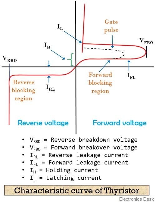
Here, the figure clearly shows the 3 regions of operation of the thyristor. As in the case of forward applied voltage initially when a gate trigger pulse is not applied, then the device operates in forward blocking region. But, as gate trigger pulse is also provided along with forward voltage then it causes a large flow of current through the device. This represents the forward conduction region.
At the time when a reverse voltage is provided only reverse leakage current flows through the device. But, after a certain reverse voltage, the device suffers from avalanche breakdown and this voltage is termed as the reverse breakdown voltage of the device.
Static characteristic of Thyristor
- The thyristor is a current controlled device. As a large anode current is controlled by some small value of gate current.
- After applying a triggering pulse, the device functions as a rectifier.
- Even if trigger pulse is provided, the device does not conduct in reverse biased mode.
- If anode current once surpasses the latching current, then removal of gate pulse does not off the thyristor.
- Proper conduction through the device only takes place when anode current exceeds the holding current.
Applications of thyristor
- In controlling systems: These are widely used in controlling ac as well as dc motors.
- In transmission lines: Employing thyristors in transmission lines improves their power factor.
- In switching applications: As they have a tremendous ability to switch between on and off state. Thus, majorly used in switching applications.
- In HVDC transmission: Thyristors have now become an essential part of high voltage transmission lines.
Key terms related to Thyristor
- Latching current: Latching current is that minimum current that flows through the device in forward biased condition. Once the device reaches this particular value then the device completely starts conduction even after the removal of the gate pulse.
This current is associated with the turn-on process of the thyristor. Its value is somewhat twice or thrice the holding current. - Holding current: Holding current is that minimal current that flows through the device in forward condition but below this particular value the device stops conduction. This current is related to turn off the process of the thyristor.
Thyristor because of their switching action and rectifying ability are widely used power semiconductor devices. These are majorly used in relay and phase controlling systems.
its very helpful for me