Antenna Impedance is related to the electric and magnetic fields and is defined at the terminal point of the antenna system as the ratio of voltage or current across the particular terminal.
The impedance of the antenna is a crucial parameter of the antenna system.
Content: Antenna Impedance
Introduction
Generally, transmission lines are used to feed antennas. And it is necessary to know the impedance of the point where the transmission line is to be connected.
This is so because an antenna can be either transmitting or receiving one. But to transmit the maximum available power or to receive the actually transmitted power, impedance plays a crucial role and must be necessarily known.
Impedance of Antenna
We know that antenna is designed to integrate the electric field and magnetic field so as to generate voltage and current that actuates the electrical device.
So, in order to have the required field and circuit quantities, the field to circuit transition with respect to impedance must be properly considered.
Basically, the antenna impedance shows dependency on factors like operating frequency, feeding method, geometrical orientation along with the effects of surrounding objects.
The impedance of the antenna is in terms of electric and magnetic fields are defined as the ratio of the electric field to that of the magnetic field at the specific points.
There are various methods that are used for calculating the impedance of the antenna are:
- Boundary value method,
- Poynting vector method and
- Transmission line method
However, mostly boundary value method is used for impedance calculation.
- Basically, in boundary method, the impedance is obtained by applying the boundary conditions that represent the absence of the tangential electric field component at the conducting surface. This determines the ratio of applied emf to that of the current i.e., impedance.
- While in the Poynting vector method, the Poynting vector i.e., the power density is integrated over a closed surface (generally a sphere of extremely large radius R where R must be greater than or equals to 2L2/λ, where L represents the largest dimension of the antenna which is considered).
- In the transmission line method, the antenna is assumed to be a transmission line and this method is most convenient when applied to biconical antennas.
So, by the use of any above-given method when the actually radiated power flow is calculated then by using basic relations, self and mutual impedances are determined.
Self Impedance
The impedance of the antenna is of great significance at the point where the transmission line is to be connected. As the transmission line carries the radio frequency power and is connected at the input terminal of the antenna thus is said to be antenna input impedance.
Sometimes also known as feed point impedance as the antenna is fed at this particular point. Another name given to it is driving point impedance due to the reason that the transmission line carrying the RF power that drives the antenna is connected at this particular point.
As we have already discussed that may it be transmitting or receiving one, but the transmission line must be such that it must provide the maximal amount of power from transmitter to antenna or it must extract maximal energy from the antenna to provide it to the receiver.
Thus, the terminal impedance is of great significance.
The figure below represents the impedance by the antenna to the transmission line using the two-terminal network: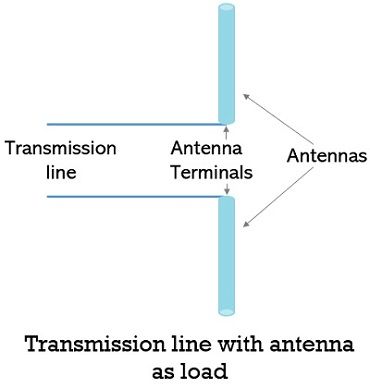 Here the entire system is replaced by equivalent impedance ZL as shown below:
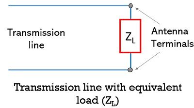
So, when it is considered that no heat loss is associated with it and it is placed away from the ground and other objects, then the terminal impedance (ZL) will be equal to self impedance (Z11) of the antenna. In this case, the self impedance will be given as:![]()
: R11 denotes the radiation resistance
X11 represents the self reactance
In case of thin linear half-wave centre fed antenna, it is given as:![]()
- It is to be noted here that self impedance is a complex quantity where radiation resistance or self-resistance is real while self reactance is the imaginary part.
For the same configuration, when it is considered that it is placed near any object then the terminal impedance will get modified. This is so because now there will be some current in the nearby active elements that will lead to cause the mutual inductance.
Thus, self impedance is the input impedance of the antenna in the absence of all other elements.
- Another noteworthy point over here is that the self impedance of the antenna is always positive. Also is similar for transmitting and receiving characteristics of the antenna.
Mutual Impedance
Mutual Impedance in a circuit is defined as the negative ratio of voltage induced in one(first) circuit to the current flowing in another(second) circuit, where the induced voltage is due to the current flowing in the second circuit which is the only closed circuit while the other is open-circuited.
Consider the coupled circuit arrangement shown below: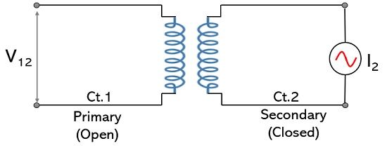
Thus, we can write the mutual impedance as: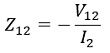
This signifies induced voltage in circuit 1(primary, open) due to the current flowing in closed-loop circuit 2(secondary, closed).
:V12 represents the voltage in circuit 1 due to current in circuit 2.
Now, consider the reverse condition as shown below: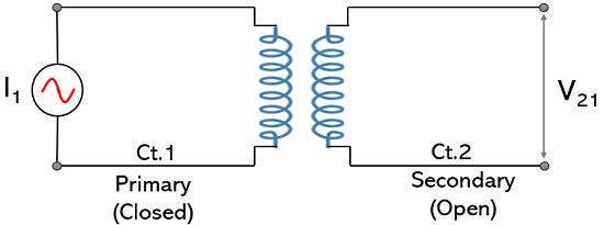
Here, the current flowing in circuit 1 induces a voltage in circuit 2. Thus, for this, circuit 1 will act as a primary closed circuit while circuit 2 will be secondary but open-circuited.
Hence, the mutual impedance will be:
: V21 represents the voltage in circuit 2 due to the current flowing in circuit 1.
According to reciprocity theorem, the two mutual impedances are equal,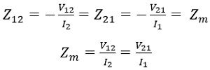
Hence, by knowing either V12 and I2 or V21 and I1, Zm can be calculated.
So, similar to the coupled circuits, multiple antennas can also be coupled and can form antenna array. But in the case of the antenna array, the input impedance not only depends on the self impedance of the single antenna but also the mutual impedance of other antennas as well.
Thus, mutual impedance shows dependency on:
- The existing phase relationship between induced and the original current,
- Magnitude value of the current induced in the circuit,
- The conditions of tuning of the secondary antennas.
In mutual impedance, it is said that the magnitude of the induced current due to coupling is maximum when the circuits are closely placed in parallel orientation and this reduces with the increase in distance of separation.