Antenna Temperature, in reality, is not the actual temperature of the physical device(antenna). Basically, Antenna Temperature is defined as the temperature of the region present near and distant to the surroundings that are coupled to the antenna via radiation resistance.
It is also known as antenna noise temperature and is not an inherent property of the antenna but is a parameter whose value is affected by the region where the antenna is located and radiating.
Antenna Temperature is denoted as TA.
Introduction
On the general basis, it is said that every radiating object possesses a physical temperature more than absolute zero. Conversely, we can say, if the physical temperature of the device is above 0K then it is supposed to radiate energy in the surrounding. The amount of radiation emitted corresponds to an equivalent temperature known as brightness temperature. This brightness temperature is denoted as TB.
But, the physical temperature of the device is never considered as the antenna temperature during measurements as in actuality the antenna temperature is associated with radiation resistance.
Basically, when we consider an ideal lossless antenna then despite considering the physical temperature of the device, antenna temperature is the one which is considered in regard to distant regions of the space. Generally, the region in space is that considerable region in the nearer surroundings which shows coupling to the antenna through radiation resistance.
This shows that the antenna temperature is not inherently associated with the device but is associated with those sections where the antenna is focusing. Thus, for antenna temperature, it can be said that the receiving antenna acts as remote sensing and temperature measuring unit.
Antenna temperature is a scalar quantity and single-valued function.
What is Radiation Resistance?
Radiation resistance is a virtual resistance and acts as a part of antenna feed point resistance. It is associated with the feed point of the antenna where some electrical resistance exists through which emission of electromagnetic radiation takes place.
We know in radio wave transmission a transmitting unit connected to the feed points of the antenna provides an electrical signal to it. The antenna further converts the electrical signal into equivalent radio waves. In this scenario, the signal from the transmitter is absorbed by the antenna, but with certain resistance at its input terminals.
As in electrical circuits, resistance is considered as an opposition which the conducting material offers to the flow of alternating current. But as we have said in the beginning itself that it is a virtual resistance and corresponds to the loss of energy by the antenna in the form of radio waves. Thus, it is given the name radiation resistance.
So, technically, the radiation resistance is defined as that value of resistance which radiates similar power that is getting radiated by the antenna in the form of radio waves when the applied input current to the antenna is passing through it. Radiation resistance is denoted by Rr.
The two crucial factors on which the radiation resistance of antenna depends are the geometry of the antenna and the frequency of operation of the antenna.
Antenna Temperature (TA) Analysis
The figure given below represents a circuit with a resistor having value R at a specific temperature Tr: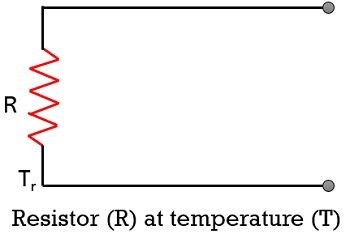
So, for the above-given arrangement, the noise-power per-unit bandwidth present at the terminal resistance R, at the given temperature will be: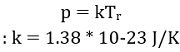
Here, p represents the power per unit bandwidth and its unit is W/Hz,
Tr corresponds to the absolute temperature of the resistor in kelvin.
- Now, suppose in the given arrangement, the resistor is replaced by a lossless antenna present inside an anechoic chamber with radiation resistance R, at temperature Tc. This discussed arrangement is shown in the figure below:
So, if Tr is equivalent to Tc, then the power per unit bandwidth will be the same as that in the case of the one which is present at the resistor terminals i.e., kTr. This is so because in both cases, an equal amount of impedance is offered by the terminals.
But a noteworthy point over here is that the noise power will be different in case the temperature of the surrounding (T) changes.
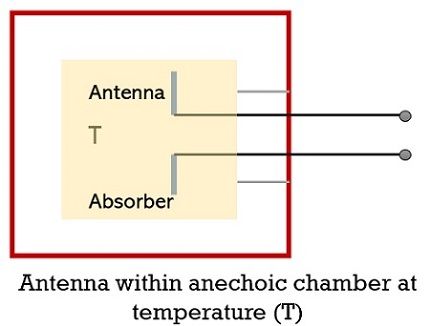
- Now, proceeding further, suppose, the antenna unit is not enclosed within an anechoic chamber but is pointed towards the sky having temperature Ts. This is shown in the below-given figure:
So, in this case also, if Ts is equivalent to Tr then the noise power per unit bandwidth will also be the same as the initial case. Thus, we can say, that the noise temperature of the antenna TA is nothing but Ts as here the complete antenna pattern is subjected to the sky temperature Ts.
To measure the distant temperature, the use of an antenna is required which acts as a passive remote sensing device. And such antennas are known as radio telescopes.
Under this measurement, a comparison between the antenna noise temperature and resistor temperature is made by making an alternate connection between antenna with the receiver and resistor with the receiver.
In case of no difference,![]()
So, basically, the noise temperature TA is same as sky temperature TS and is not the physical temperature of the antenna. However, for the completely lossy resistor shown in the first figure, the noise temperature TA will be equivalent to its physical temperature. Here TA is the antenna temperature calculated against sky temperature in the direction of the antenna beam towards the sky.
Hence, for the remote sensing device i.e., radio telescope the power per unit bandwidth will be:![]()
- Now, if we keep the power per unit bandwidth as a frequency-independent factor then we will get the overall power simply by multiplying the above equation with bandwidth. So,
![]()
Here, P denotes the total power in watts and B corresponds to the bandwidth in Hz.
- Further, if we consider the factor of effective antenna aperture Ae in the antenna arrangement shown in the third figure where the beam is in the direction of radiation source producing power density per unit bandwidth i.e., flux density (S). Then the power obtained from the source:
![]()
Here the two consecutive above-given equations represent overall received power. Thus, on equating the two we will get:![]()
Thus, the flux density S will be given as:
The antenna temperature from the above equation will be:
Where the unit of TA is K.
So, from the above analysis, we can conclude that the noise (antenna) temperature is crucially dependent on the power produced per unit bandwidth along with the effective aperture of the antenna.