Radio Wave Propagation deals with the behaviour of radio waves when the waves travel from one end to another. It is sometimes known as simply wave propagation or propagation of electromagnetic waves. Radio wave transmission is a quite prominent method by which information can be transferred from one end to another.
Radio wave propagation is used in radio communication in order to transmit signals to short or long ranges. Along with this, it also finds applications in radar, direction finding, remote machine controlling, etc.
Content: Radio Wave Propagation
Introduction to Radio Waves
We have discussed antennas in our previous content, where we have seen that high-frequency current in the antenna terminal gives rise to electromagnetic energy which exists in the form of waves. These waves exhibit the properties of light. Radio waves in space oscillate in free space with the velocity of light i.e., 3*108 m/s. These are electromagnetic waves that consist of electric and magnetic field components. It is traversed in nature i.e., the components oscillate perpendicular to the direction of motion.
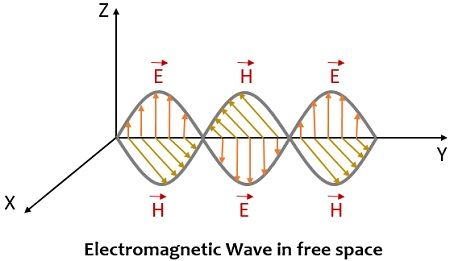
It is to be noted here that the initial polarization produced by an antenna depends on its orientation w.r.t ground. An antenna placed in a horizontal and vertical manner will produce horizontally and vertically polarized waves respectively. It is considered that in general, all waves maintain the type of actually produced polarization during its propagation as well. During propagation, waves encounter phenomena’s like reflection, refraction, diffraction in the path.
What is Radio Wave Propagation?
Radio wave propagation is associated with the phenomena that occur when a wave travels between transmitter and receiver. However, the wave can travel between transmitter and receiver in two ways:
- By propagating in free space
- By guided within a medium such as coaxial cable or waveguide.
When the wave is allowed to propagate through free space, then during propagation, the available spectrum must be shared amongst the existing users in a proper manner. This includes providing services to the devices which are in close geographical proximity to each other. Furthermore, in this case, there are high chances of interference between the devices operating at nearly the same frequency.
In case, when propagation takes place through a guided media then the signal is subjected to less attenuation with other users. Also, in this case, the user gets access to the full range of frequency band. When a wave propagates through the earth environment then the manner of wave propagation does not depend only on the properties of waves but also on the environmental conditions. The effect of the medium in which the waves propagate is of great importance as it accounts for the intermediary objects in the path.
The environment through which the radio waves propagate includes discontinuities like hurdles or variations in medium parameters. For practical radio wave propagation, the earth and the objects present in its surroundings are highly considerable.
The behaviour of wireless channel must be properly understood if we need to design an effective radio communication system irrespective of the distance of transmission. Maxwell’s equation adequately describes the behaviour of radio waves. Henrich Rudolph Hertz also performed some experiments that verified the theory proposed by Maxwell’s.
From Maxwell’s equation, one gets the idea about the basis of the explanation of wave propagation in space. Along with this, it also tells about what nature electric and magnetic field exhibit within a conducting and insulating waveguide.
When a transmitting antenna radiates a signal then generally it gets spread over a quite large region and so at the receiving antenna, the received power is of comparatively small fraction than actually radiated one. This corresponds to the transmission loss (nearly of the order 1015 to 1020) existing between two antennas. And from this loss, one can conclude whether the signal which is received is of any use or not.
Modes of Radio Wave Propagation
Till now we have got the idea that when a wave is emitted from one of the ends, it reaches the other end propagating in free space or any medium. The way or manner in which the radio waves move classifies various propagation mode. These are regarded as modes of propagation of radio waves. However, this classification is also associated with parameters like operating frequency, the existing range between two antennas, etc.
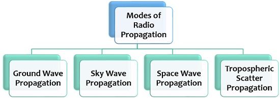
Let us now discuss each type of radio wave propagation separately.
Ground Wave Propagation: It is also known as surface wave propagation in which the radio waves transmit by passing through the semi-conductive surface of the earth. Here the transmission of waves takes place at a region close to the surface of the earth travelling beyond the horizon. This mode of propagation requires vertically polarized waves as the horizontally polarized waves in this case will get absorbed by the earth.
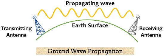
Here the propagating waves follow the earth’s curvature. It mainly suits very low (VLF) or low frequency (LF) signal transmission.
- Frequency range: 30 kHz to 3 MHz
- Transmission distance: 100 to 1000 km
Beyond frequency of 3 MHz and distance of 1000 km, attenuation of the transmitted signal by the earth begins.
Sky Wave Propagation: This type of wave propagation makes use of the upper atmospheric layer i.e., the ionosphere to transmit the radio waves. Here the signals radiated by an antenna bent back towards the earth by getting refracted from the ionospheric layer. This upper atmospheric layer is ionized that means electrical charges exist in it and the reason behind this is the ultraviolet radiations from the sun. The ionosphere begins at 60 km above the surface of the earth and extended upwards up to about 400 km. It suits high frequency (HF) propagation.
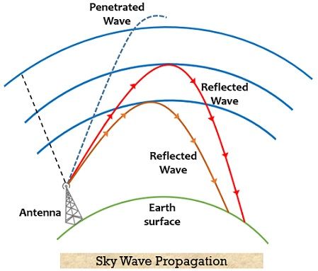
- Frequency range: 3MHz to 30 MHz
The electromagnetic waves transmitted from one end of the earth’s surface reaches the other end when TIR takes place at the ionospheric layer of the atmosphere. Thus, it suits very long-distance radio communication.
Space Wave Propagation: It is also called direct wave propagation and offers a line of sight communication. Here the signal from the transmitting antenna propagates in a straight line towards the receiving antenna. It neither follows the earth’s curvature nor undergoes refraction by the ionospheric layer of the atmosphere rather propagates horizontally from one end to another.
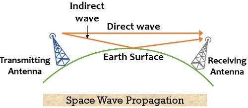
This mode of propagation takes place in the tropospheric region of the earth’s atmosphere which is present up to a distance of 16 km from the ground. It has mainly 2 components direct component and indirect component. It is clearly shown in the above figure that one wave is directly transmitting from one antenna to another while at the same time, a wave is getting reflected from the ground and reaching the receiving antenna.
The wave that reaches the receiving antenna after getting reflected is 180⁰ out of phase w.r.t the direct wave as the two waves reach the receiving antenna by taking different paths. At the receiver antenna, the strength of the signal is obtained by the vector addition of direct and indirect waves. It is sometimes called tropospheric propagation.
It shows suitability for signal transmission that have a frequency of more than 30 MHz. Such signals are generally, VHF, UHF and microwave signals. In radio communication, the transmitting distance of direct waves is related to the height of transmitting and receiving antennas. The distance from the transmitting antenna to the horizon is given as:
![]()
:ht corresponds to the height of the transmitting antenna
In order to get the practical distance, D for straight wave transmission, we must consider the height of the receiving antenna as well. So,
![]()
hr corresponds to the height of receiving antenna.
It is to be noted here that the height of both the antennas is in feet.
Tropospheric Scatter Propagation: It is sometimes called forward scatter propagation or scatter propagation and is suitable for VHF, UHF and microwaves. In this, the waves propagate through forward scattering due to the irregularities of the troposphere. This propagation technique uses the properties of the troposphere. This mode offers reliable communication between 160 km to 1600 km.
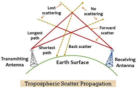
It is called so because in this case, the propagation occurs beyond the horizon i.e., the fine layers of the troposphere. This type of propagation sometimes leads to the production of unwanted noise or fading.
It is to be noted here that other than these four modes of propagation, propagation occurs through the inversion layer of the troposphere and this case is named duct propagation or super refraction.